Isn’t that a handful? What exactly is a “Universal Robot Configurer” anyways?
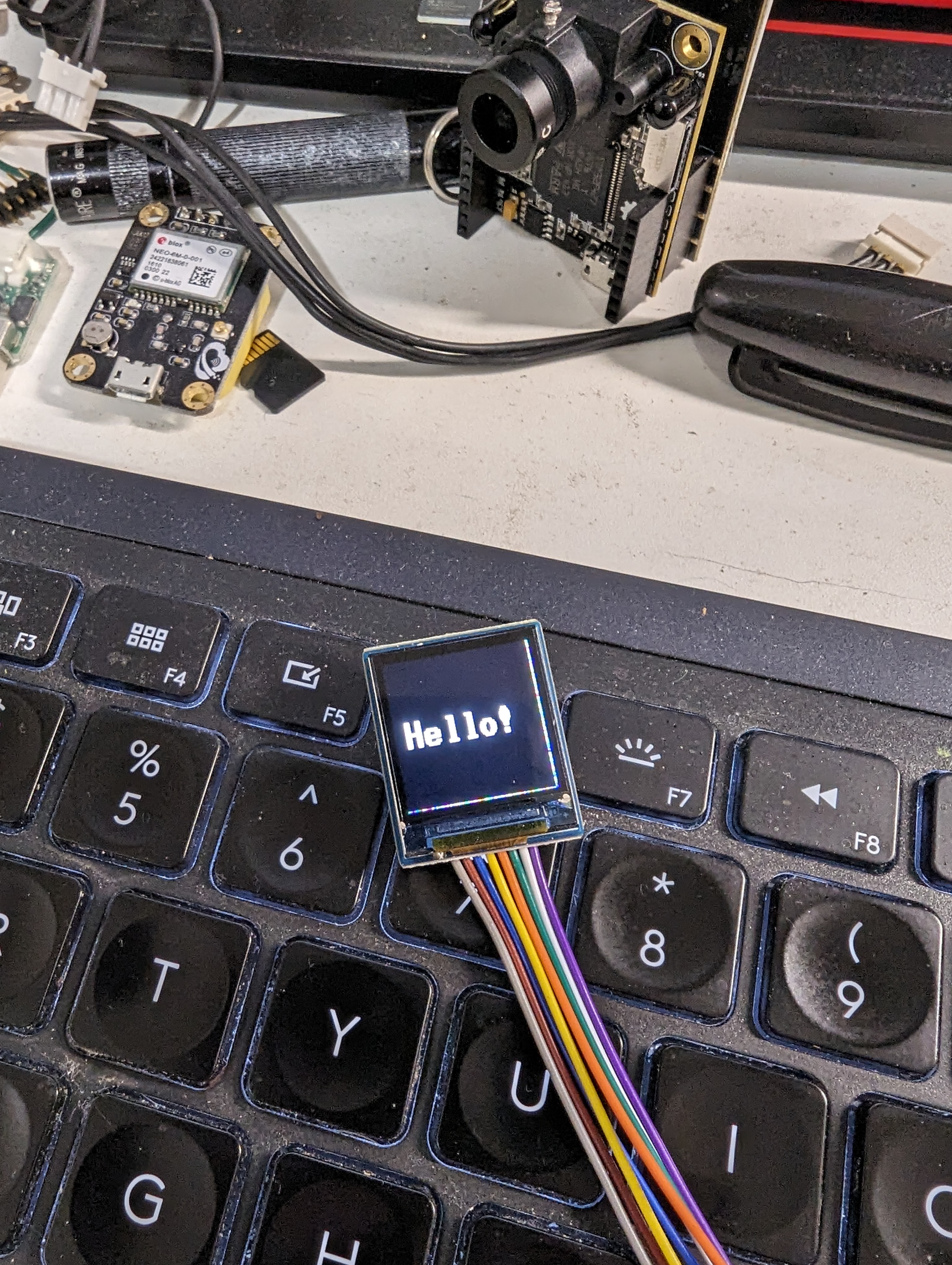
This is a project that basically fell into my lap, when I started trying to improve my handheld failsafe trigger for my RoboMagellan robot. I started off with a tiny monochrome 0.91″ OLED LCD panel, 128 x 32 pixels, that could only draw using this tiny font.
This worked well, and it gave me what I neeed, but I wanted a better screen on it. I redesigned the head so that it was removable, and put in a small LCD panel that I had picked up from Waveshare. This new screen is a 0.85″ display, but it is color, and 128 x 128 pixels.
It had some driver issues, but it would still be nicer than the tiny little OLED screen, and it supported more fonts.
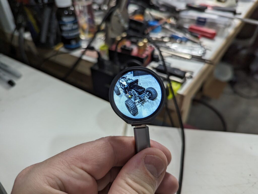
About this time, I was working on building a touch-enabled GUI for my 1.28″ round display that I had mounted on the Tabletop robot. It ended up being very versatile, so I redesigned the failsafe head again, this time putting on the round screen.
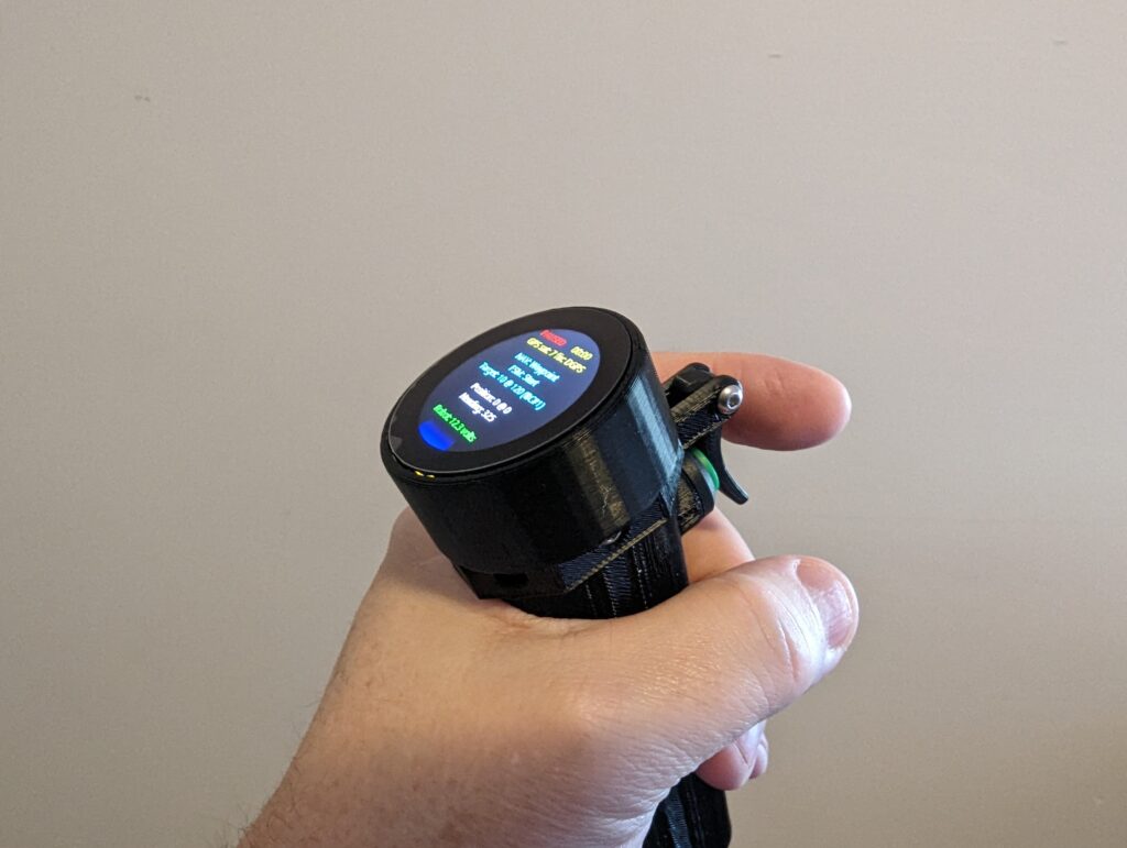
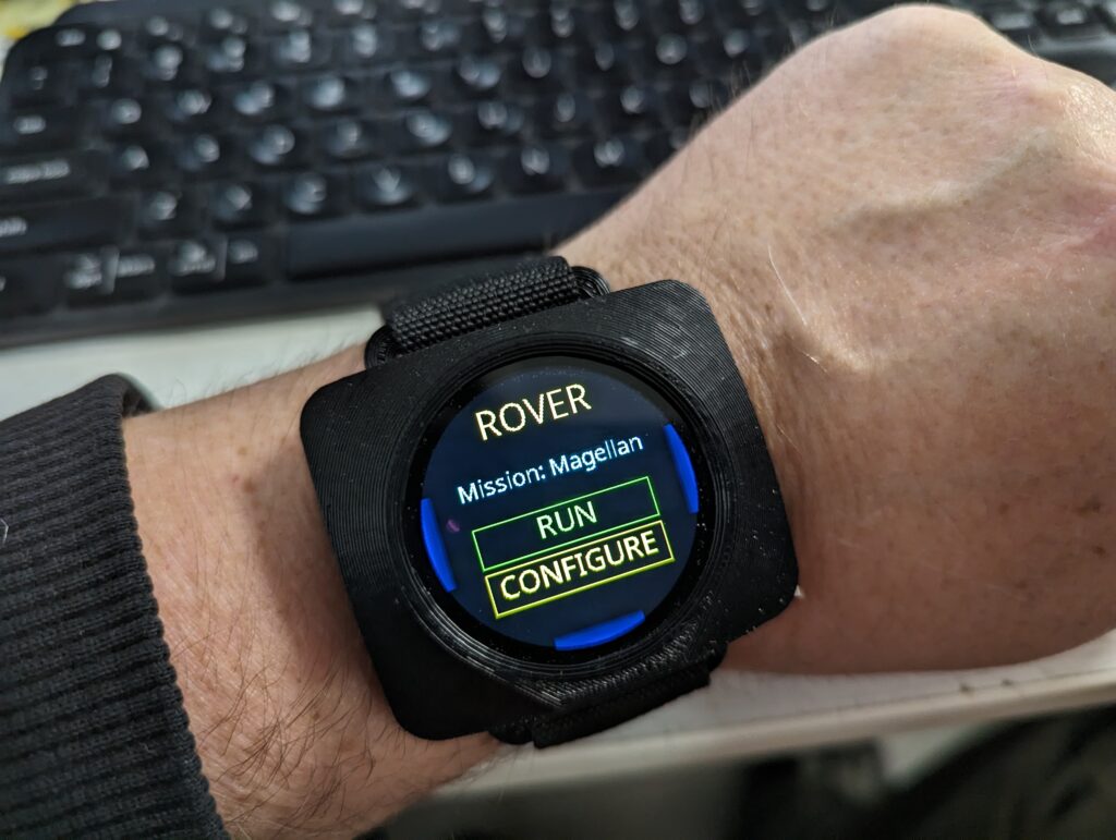
Now I felt like I was onto something. It was about this time I was introduced to ESPNow, which is a peer to peer radio link that ESP32 chips can do. I immediately got the idea that this could be used to talk to all my robots (assuming I put an ESP32 in each one), and it would allow me to configure them, launch missions, and so on. Waveshare started selling a 1.28″ round touch screen with a built-in ESP32-S3, so I ordered a couple of those, and decided to change the form factor of the failsafe to be more of a smart-watch like wearble.
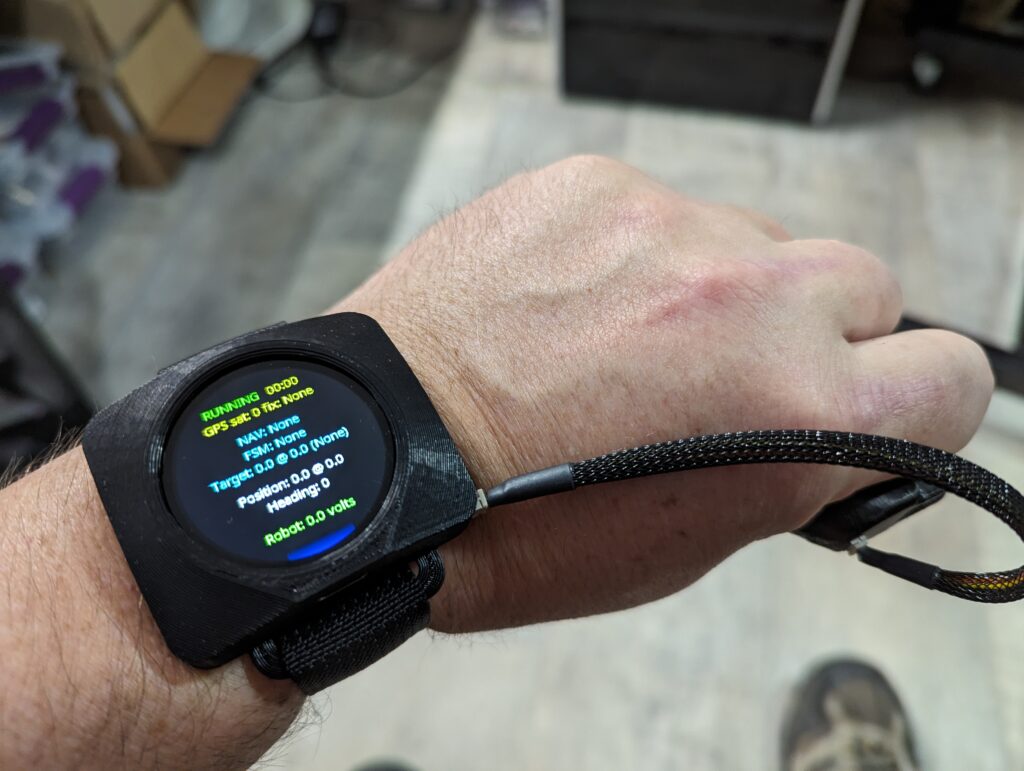
So now, here I am, with this neat little smart-watch like thing, that I can program in MicroPython, and it has a full touch interface. You can swipe left and right to switch screens, and swipe up to go back. I can disconnect the failsafe trigger if I don’t want it – it simply plugs in to a small 3-pin connector on the side of the case.
Its not really intended to be an actual smart watch – its a little on the bulky side for that, because I’ve got an enormous 1000mAh battery inside. But it will work with my robots, regardless of whether I am on my local Wifi network or away from home, in a sports field running a RoboMagellan mission.
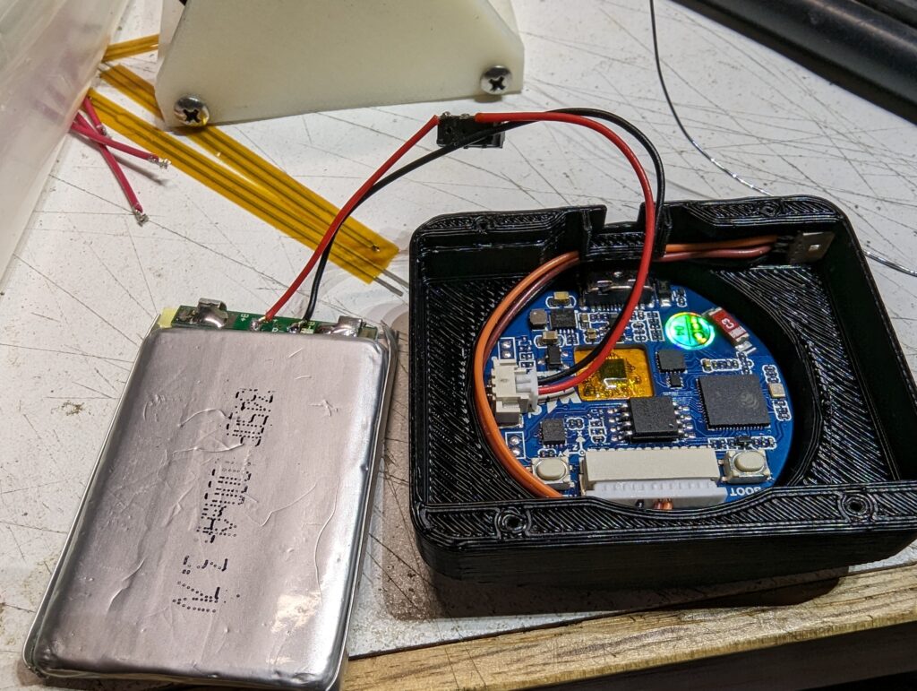
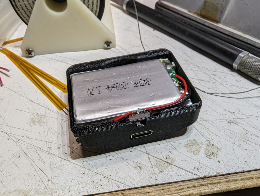
Here are a few pictures showing the insides – it is remarkably simple, just the screen/board combo, my 3-pin trigger connector, a battery with a slide power switch soldered in place, and the battery itself. And of course, a 3D printed case and a few M1.4 machine screws to hold the back in place. I use a piece of 1″ nylon webbing as the strap, with a cam buckle to hold the strap in place.
The USB-C connector on the board allows you to both charge the battery, and to use MicroPython tools like rshell to do development. I’m very happy with how this turned out, and I continue to work on the software side of things to try and make it work better, and flesh out everything it needs to do in order to be useful for my robots.
In addition to working on my RoboMagellan robot, I decided to start a somewhat smaller and less ambitious project.
This is what I call a tabletop robot, because it is very small and will roll around the top of a table. One thing it should never do is fall off the table, and it has two down facing time-of-flight laser sensors in the front to help avoid that.
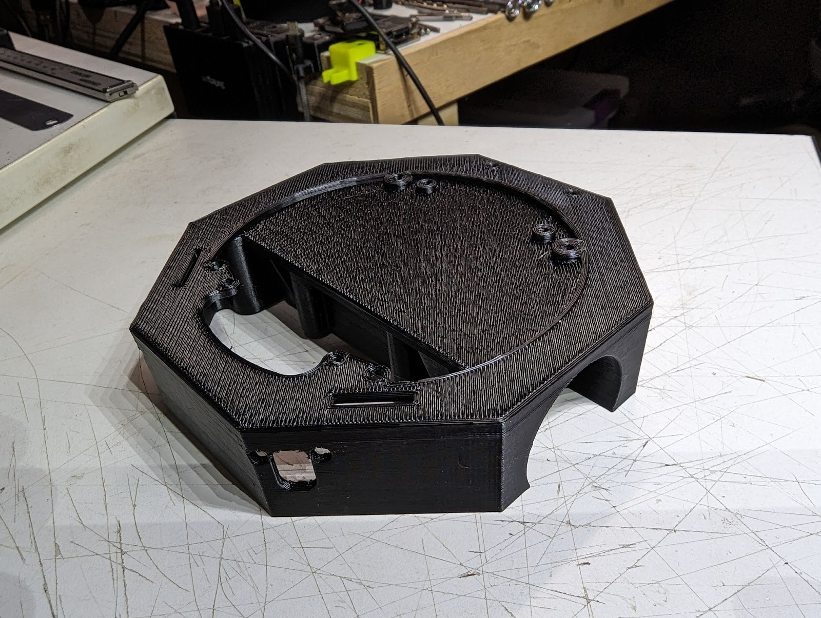
I’ve 3D printed the first version of the base of this robot (its a six hour print job).
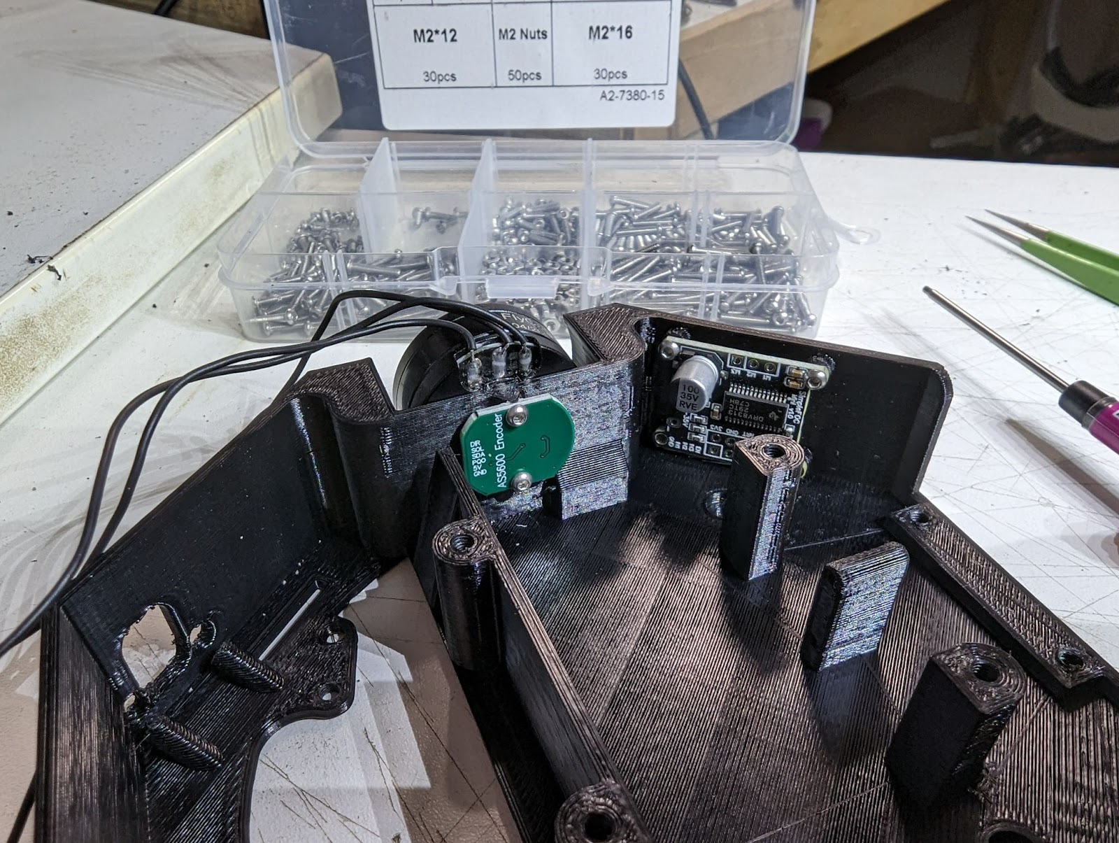
I always end up doing a few versions of complex parts, because you never get everything perfect the first time. In the image below, I’m test fitting a couple of the boards needed – the motor encoder, and the motor driver board, as well as the motor itself. One change I had to make to the CAD model already – I forgot to include a hole to run the motor wires though.
This robot is my first wheeled robot with brushless gimbal motors, and I’m looking forward to seeing how well they do.
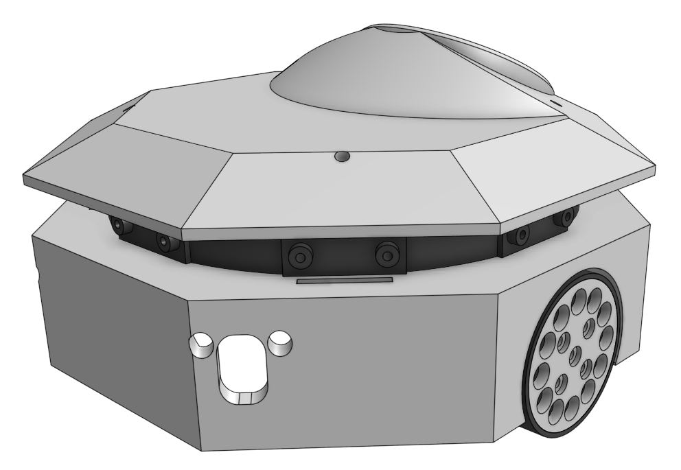
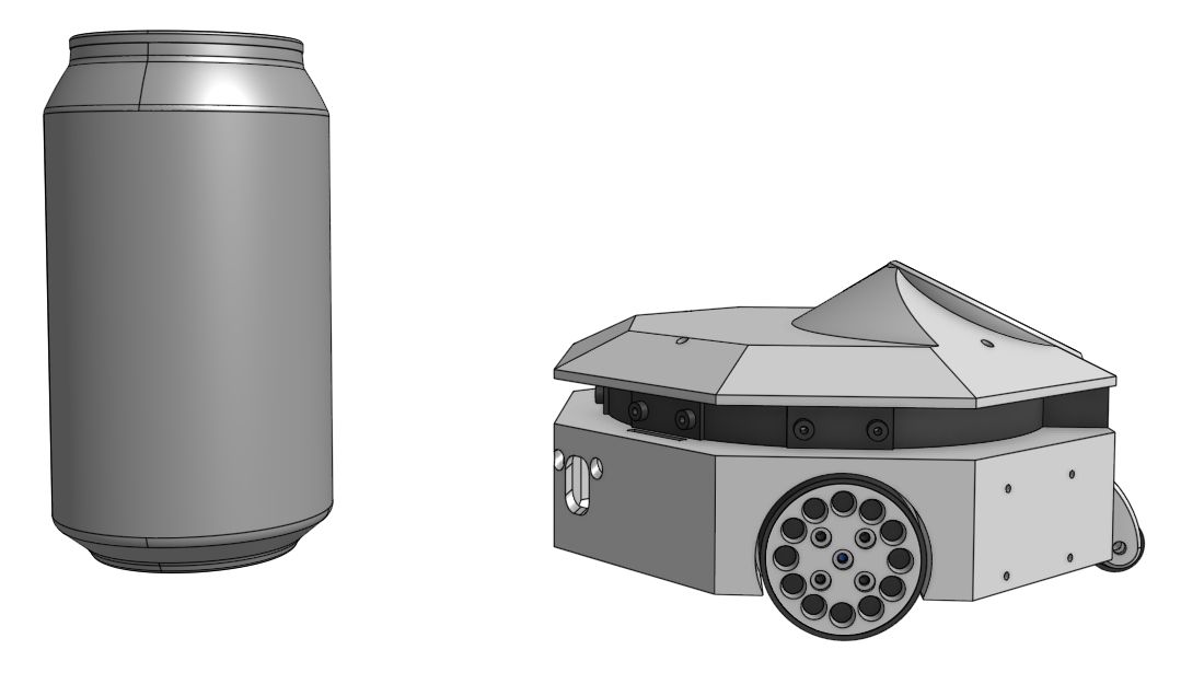
To give a sense of scale of this robot, here’s a render of it next to a normal 355ml (12 oz) pop or soda can:
Its going to be small and (hopefully) rather cute, but at the same time, very capable.
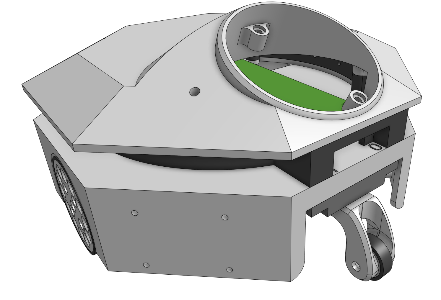
That touch screen will be how I can interact with the robot, and how it can display status and information about what it is doing.
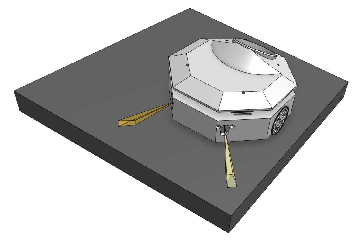
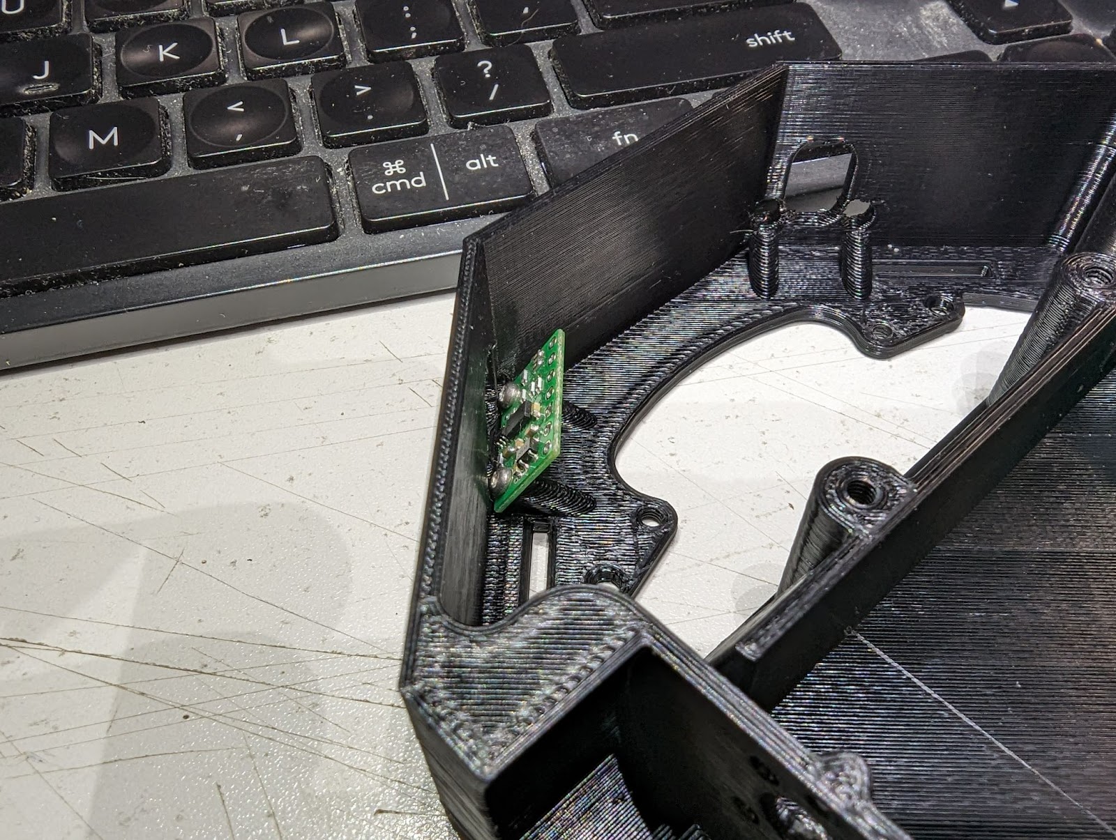
Here’s another picture, showing the chassis (upside down), with a laser range finder mounted.
The board, which will be a VL53L1X (from Pololu) points down at a thirty degree angle, and points out to the side at a forty-five degree angle. There will be a matching sensor on the other side. These range sensors will allow the robot to sense the edge of the table, either in front or if the robot is right next to the edge, from the side.
Inside the robot will be four different microcontrollers – all four of them will be Waveshare RP2040-Tiny boards. These are great little machines – they run MicroPython, and are small and very cheap (like $6 CAD each). The main RP2040 will be connected to the touch screen display, and it will talk to the others over a serial bus. The first device on the bus will be a sensor interface device, and it will gather all the sensor data (except the motor encoders – more about those later) and be able to give it to the bus master on request.
The other two RP2040’s will be motor drivers, for the brushless gimbal motors. Each motor gets a dedicated microcontroller. They will be responsible for controlling the motors and providing feedback to the bus master. They will implement a form of closed loop control by enforcing the requested speed using a PID loop with the encoder as the input sensor. Overall, the robot is going to implement a subsumption-like set of behaviors, similar to what David Anderson uses on his smaller robots. All the code will be written in MicroPython.
A lot has happened since I last posted here, and I’ll be switching the focus of this blog to be more robotics stuff, although I will probably add in a few other bits and pieces as things go along.
Ever since I saw they were running RoboMagellan competitions back in the early 2000’s, I’ve wanted to build a robot to compete. I did build an outdoor navigation robot while I was working on a robotics contract for a University in the US back in 2008, but I didn’t know anything about outdoor robots at the time, and ended up choosing a poor chassis to start with. I also didn’t spend nearly enough time on the software, the robot was too large and heavy, and couldn’t figure out how to deal with the (rather noisy) LIDAR data I was getting.
Video of that robot running in my back yard
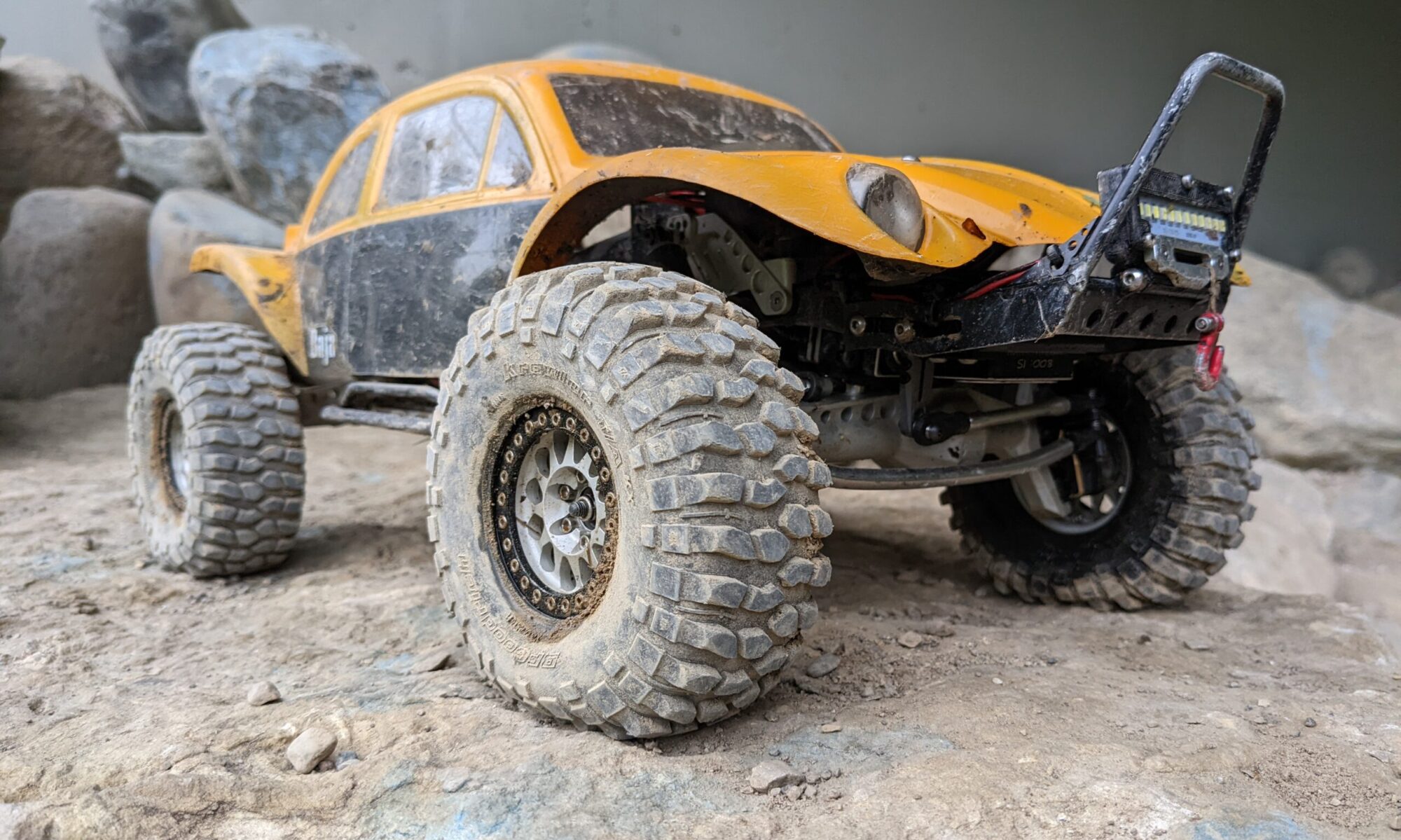
I spent a couple years during the pandemic getting into RC Rock Crawlers, and built what I consider to be a rock-solid, extremely capable rock crawler vehicle.
Here’s a video of it in action:
Video of my RC Rock Crawler, in the wild
I recently got back into Robotics after a roughly five year hiatus.
I decided after a month or so of playing around with a couple walking robots that I really wanted to build a RoboMagellan robot, and I was going to use my yellow Baja Bug rock crawler as a base.
One of the safety requirements of a RoboMagellan robot is having some kind of remote failsafe, which will stop the robot if you let go. We run these robots in public parks and areas like that, with lots of people around. Being able to stop the robot instantly is a good thing, both for the health of bystanders and the robot itself.
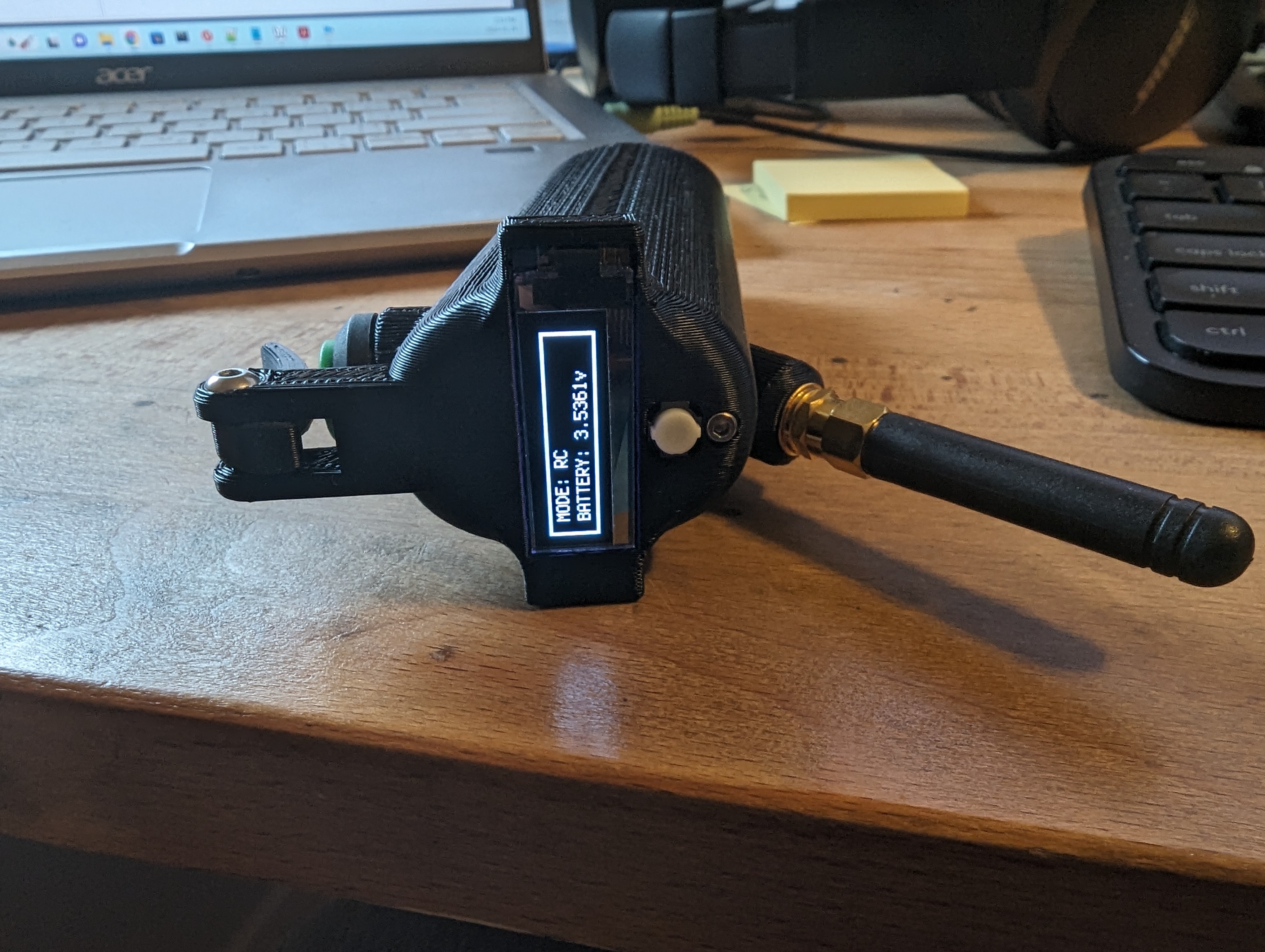
I worked on the failsafe remote as a “getting started” project. I wanted something reasonably ergonomic, since I would be paying more attention to the robot than where the failsafe button is. I wanted something where I could see what it is doing, that would allow me to change from autonomous robot mode to remote control, and that also let me know how much battery is left, so I don’t run out of battery and die half way through a run.
So I needed the following parts to make up this failsafe handheld remote:
3D printed case
Trigger button
Mode button
Some kind of display
Microcontroller with an RF transceiver
Battery (single cell lipo)
Step up/step down voltage regulator to get a constant 3.3 volts
Power switch
I needed some way to charge the battery, since I planned on using a single cell Lipo battery. The microcontroller had to be capable of running MicroPython or CircuitPython, since that is my language of choice for embedded programming now.
I did some research, and Adafruit had an excellent option that took care of almost everything. Adafruit Feather RP2040 RFM69 Packet Radio checks all the boxes and then some – it runs Circuit Python, it has a nice 915 MHz transceiver onboard, and it can run off a single cell lipo, and charge that lipo from USB power.
I ordered two from Digikey (Digikey carries a lot of Adafruit’s stuff, and has much better shipping to Canada than almost anywhere). I had a 620 mAh lipo battery on my work bench from an earlier experiment, and I also had a couple of those neat little 0.91” OLED LCD panels that are controlled using I2C. You can get them almost anywhere, I think I ordered them off Amazon although I think they are much cheaper from other sources like Ali Express.
I did some bench testing to make sure that the RP2040 could talk to both the LCD panel and the radio, and then started CAD modeling the case. I ended up with this:
After 3D printing the case in ABS, and making a few adjustments, I got this:
The grey cable is a USB-C extension cable I got off Amazon, and allows me to charge the battery, which is in a box under the microcontroller. The on/off switch is also on the bottom, next to the USB port.
The ugly looking resistors near the top of the microcontroller board form a voltage divider, so I can measure the battery voltage (which is almost always more than the 3.3v the analog to digital converters on the RP2040 can handle).
In RC mode, it looks like this:
Switching to autonomous mode looks like this:
Pressing the trigger while in autonomous mode looks like this:
Easy to use, easy to hold on to, does everything I need. I call that a successful project.
The Robot
Here are a couple of pictures showing the robot’s current state:
In the second picture I’ve added the GPS mount. I may have to relocate that onto some kind of mast, along with the IMU, but we’ll have to see how it does in actual testing.
The robot will be run from a Raspberry pi 4, running an autonomous controller written in Squeak Smalltalk. I’ll talk a lot more about my plans for the autonomous controller in a later post.
On the embedded side of things, the main microcontroller will be a WeAct STM32F405 Core Mini Board running MicroPython. There is a GPS, an IMU, and a small 1.47” LCD panel visible through the side window. It will have a small close range ToF LIDAR sensor in the front bumper (for final cone approach), and a set of 3 ToF LIDAR sensors in the back to help avoid backing into things. I’ve already installed an encoder onto the front of the motor, before it gets to the transmission, for helping with odometry.
You can see the small brass pin I machined in the above image, with a small magnet disc attached to the end. The quadrature encoder PCB is mounted to the back of the battery case, and will feed into the main STM32F405 microcontroller to keep track of how far the robot moves.
The main obstacle-avoidance and cone-finding sensor is a Luxonis Oak-D Lite (I backed their kickstarter). You can (according to the documentation) do simultaneous depth mapping and object detection (using a custom model you train), with zero CPU usage on the raspberry pi. I’m planning on training a model to do cone detection.
The RC Receiver (visible in the first robot image above, just behind the front left tire) will have the throttle and steering signals routed into the main microcontroller, and said microcontroller will produce the PWM signals for the steering servo and the motor control.
Finally, the failsafe, which is a duplicate of the Adafruit board inside the handheld remote, will talk to the main microcontroller and tell it what mode it is in, and thus how to control the motor and steering.
The Raspberry pi 4 will also talk to the main microcontroller over a serial port, and send control commands and receive sensor feedback as needed.
I think I’ll wrap it up here for now, but much more to come…
In mid-august, I brought my younger two kids (the twins, Aaron and Robin, who are 22) on a wilderness camping trip into the interior of Algonquin Park. Neither of them have ever been to the park, so it was a nice experience for them (and me).
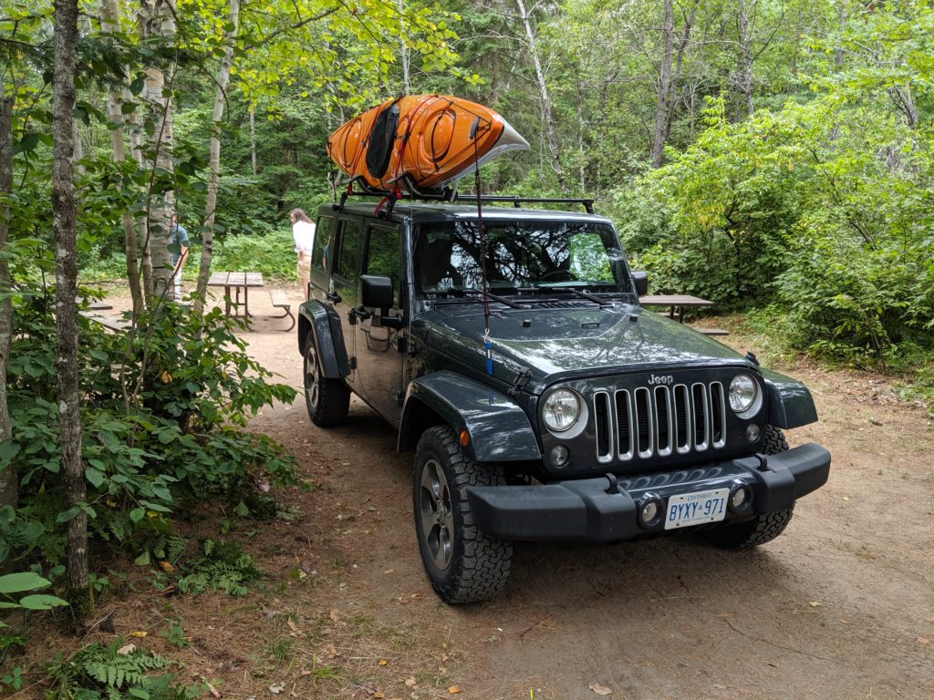
We left on Thursday August 15 at around noon, and drove to Huntsville. I had my Delta 12.10 kayak strapped to the roof of my Jeep, and we had all our camping gear in the back. We pulled into Arrowhead Provincial Park at around five, and got our site registration done. I had decided to stay at Arrowhead for the night so we could get on the lake in Algonquin early the next morning (its a five hour drive from home).
Our staging campsite at Arrowhead Provincial Park
Our campsite was a bit of a mess, with the fire pit full of bottles, cans, and even a dirty stainless steel cooking pot. We set up our two tents, and then we stopped at the park office on the way out to get dinner. When we got back all the garbage had disappeared, which was a good thing, given that we were in bear country.
The next morning we packed up our tents early, and were back on the road just before six. We reached Kearney around six thirty, and found an open restaurant we could eat breakfast at. Once we were done, we went over to Algonquin Basecamp, and picked up the paddles, pfds, and safety gear for the canoe we were renting, along with the key. A quick trip across the road to the park permit office to pick up our permit, and then we were on our way to Rain Lake (access point #4).
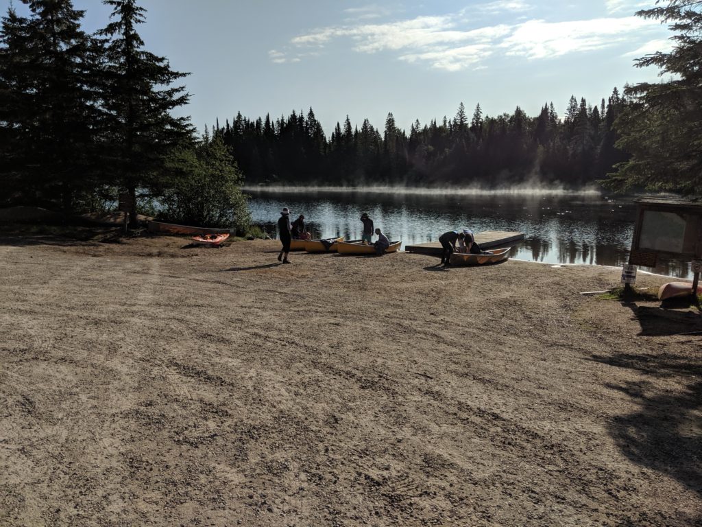
We saw a couple bull moose back from the road on our way to the lake, but I only took one picture, and it was really blurry. We got to the lake finally, found our canoe, and started loading everything up. There were a number of people loading up at the same time, although most of them were going much farther than we were.
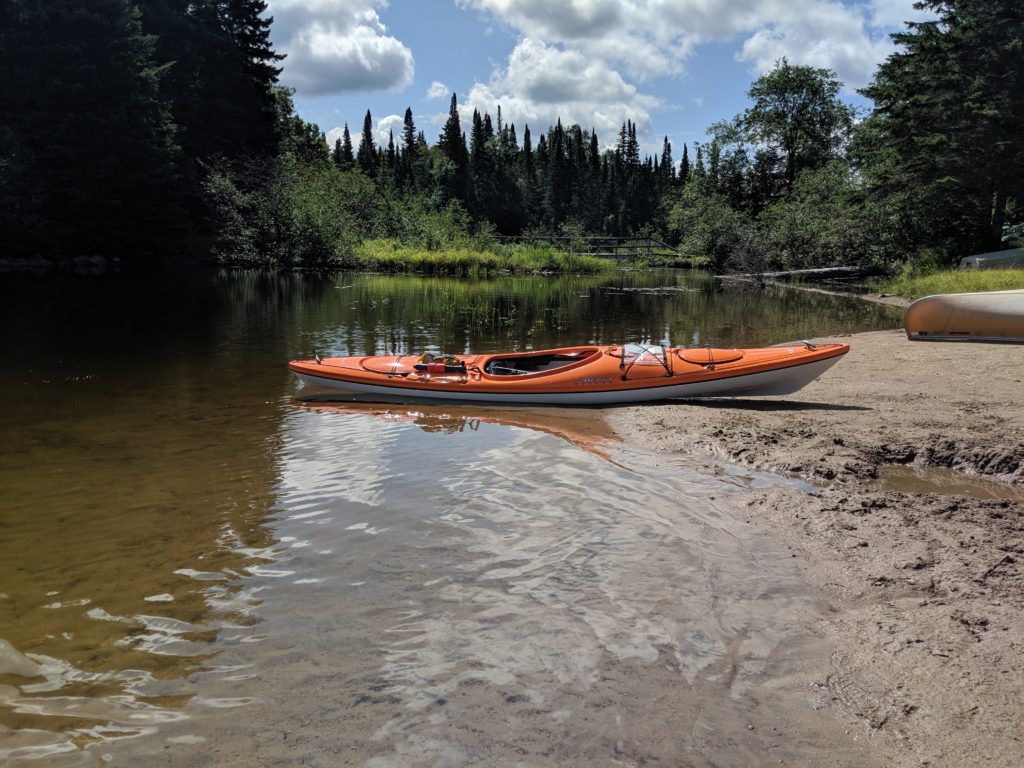
Rain Lake access point
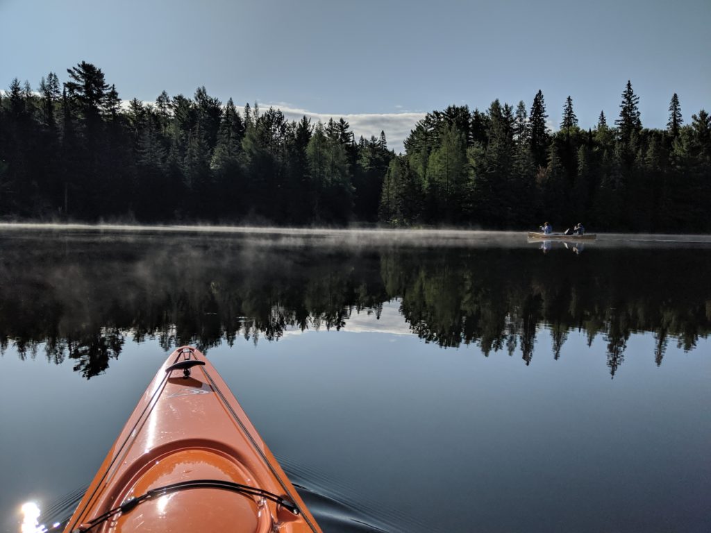
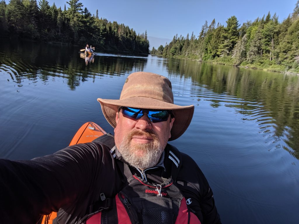
We were on the lake by about eight forty-five, and the water was like a sheet of glass, with some neat mist just above the surface along one side.
Aaron and Robin in their canoe, in the mist…The water was amazing – no wind or waves… A selfie with the boys in the background…
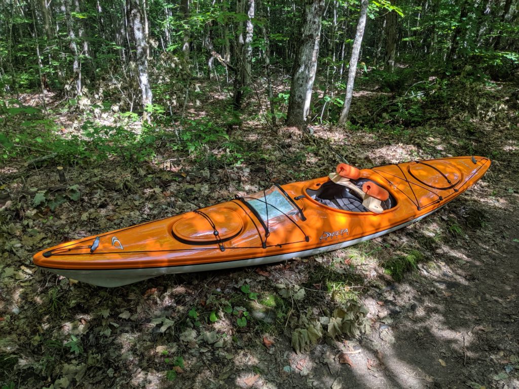
We eventually got to the end of Rain Lake (its a long skinny lake), and did the portage to Sawyer Lake. A quick hop across Sawyer, and by twelve thirty or so we were on Jubilee Lake, our destination for this trip. The kayak wasn’t too bad to portage with the yoke I had built (patterned after Kayak Camper’s Yoke), and my custom-built back-frame worked reasonably well with the dry bags carrying all my gear. I’ll do a project page in the future discussing my portage gear, so I won’t post any more information here. My Delta 12.10 kayak is nice and light, weighing in at 41 lbs, so it is pretty reasonable to carry.
We spent Friday afternoon and all day Saturday just hanging out, lazing around, exploring the lake, and generally relaxing.
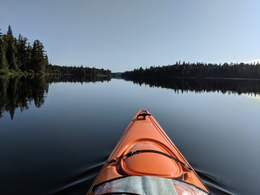
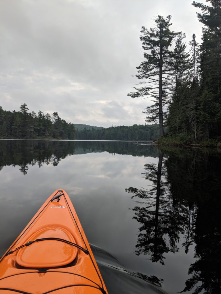
I took what is probably the nicest picture of the trip on Saturday morning, while I was out exploring the lake.
Finally, on Sunday morning we packed up all our gear, and headed back out.
Mid-portage rest
There was a strong headwind we were fighting all the way down Rain Lake, so we were exhausted by the time we got to the access point. I literally fell out of my kayak, but fortunately I had a full change of dry clothes waiting for me in my Jeep.
After a long paddle
It was a really nice trip, all in all. The last time I was in Algonquin was in 2013 with Nick, my older son. I had hoped to do a solo trip in September this year, but it turns out I have to spend a bunch of time flying back and forth to California this fall for the job, so maybe next year…